Motor Terminal Box Position

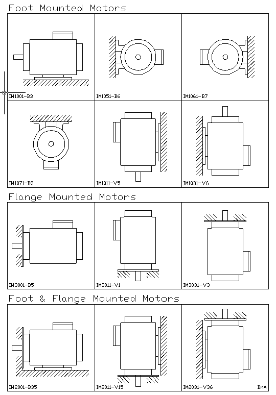
Elektrim Motors Iec Nema Mounting Positions

Elektrim Motors Iec Nema Mounting Positions

Motor Mounting Codes Drives And Automation

Motor Mounting Codes Drives And Automation

Mounting Positions Of Bevel Helical Geared Motor And Bevel Helical Gearboxes

Mounting Positions Of Bevel Helical Geared Motor And Bevel Helical Gearboxes

Dr Motor Sew Eurodrive Brakes

Dr Motor Sew Eurodrive Brakes

Electrical Installation Basic Vocational Knowledge 7 Mounting And Connection Of Motors 7 2 Connection Of Three Phase Motors

Electrical Installation Basic Vocational Knowledge 7 Mounting And Connection Of Motors 7 2 Connection Of Three Phase Motors

Motor Mountings

Motor Mountings

Motor Mountings

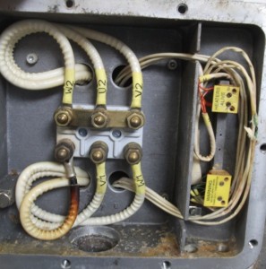
Star connection terminal motor if our power supply is 200 vac 3 phase we need to connected the cooper bar terminal in delta position it mean a connection are u1 with w2 v1 with u2 and w1 with u2 it just need to follow.

Motor terminal box position.

F1 and f2 mounting refers to the location of the junction box on an ac motor. The standard iec mounting position places the junction box on the top of the motor known as the im b3 mounting position in iec frame or f3 in nema frames. This position is where the junction conduit box is located on the left side of the motor facing the output shaft. This is the probably the most popular configuration and is the standard for the majority of motors sold in the us.

575v brake medium voltage custom motor solutions for over 40 years elektrim motors has designed and manufactured a full line of ac nema and metric iec motors for the us marketplace. F1 to f2 mounting convertibility frame size ability to be converted 56no f1 only. The f2 mounting position is a right side location facing the output shaft. The position of the motor terminal box has so far been specified indicated with 0 90 180 or 270 as viewed onto the fan guard b end figure 86.

You need to select at least 1 product to add in your comparison list. Associated product s security information. Position of motor terminal box and cable entry the position of the motor terminal box has so far been specified indicated with 0 90 180 or 270 as viewed onto the fan guard b end figure 14. Conduit boxes commonly known as terminal or junction boxes are designed to house the electrical wires between external power cables and the internal electrical wiring of an electrical motor.

Select at least one product to add to your shopping list. These boxes are able to be mounted on to motor frames. On the other hand the nema standard mounting position is referred to as f1 with the junction conduit box located on the left side of the motor facing the output shaft. Our enthusiasm for motors and commitment to exacting standards mean that elektrim motors are some of the finest longest lasting and best performing motors in the.

Turning the stator position change terminal box position on the motor by 180 degrees. Select at least one list to add to your products.

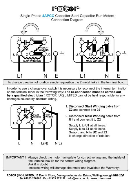
Single Phase Cap Start Cap Run Motors Rotor Uk

Single Phase Cap Start Cap Run Motors Rotor Uk

Sew Eurodrive Different Mounting Positions For Gear Units Bevel Sewing The Unit

Sew Eurodrive Different Mounting Positions For Gear Units Bevel Sewing The Unit

Https My Motovario Com File Php S 42k9

Https My Motovario Com File Php S 42k9

Https Download Sew Eurodrive Com Download Pdf 19496419 Pdf

Https Download Sew Eurodrive Com Download Pdf 19496419 Pdf

Rotary Motors For Precision Positioning What To Choose When

Rotary Motors For Precision Positioning What To Choose When

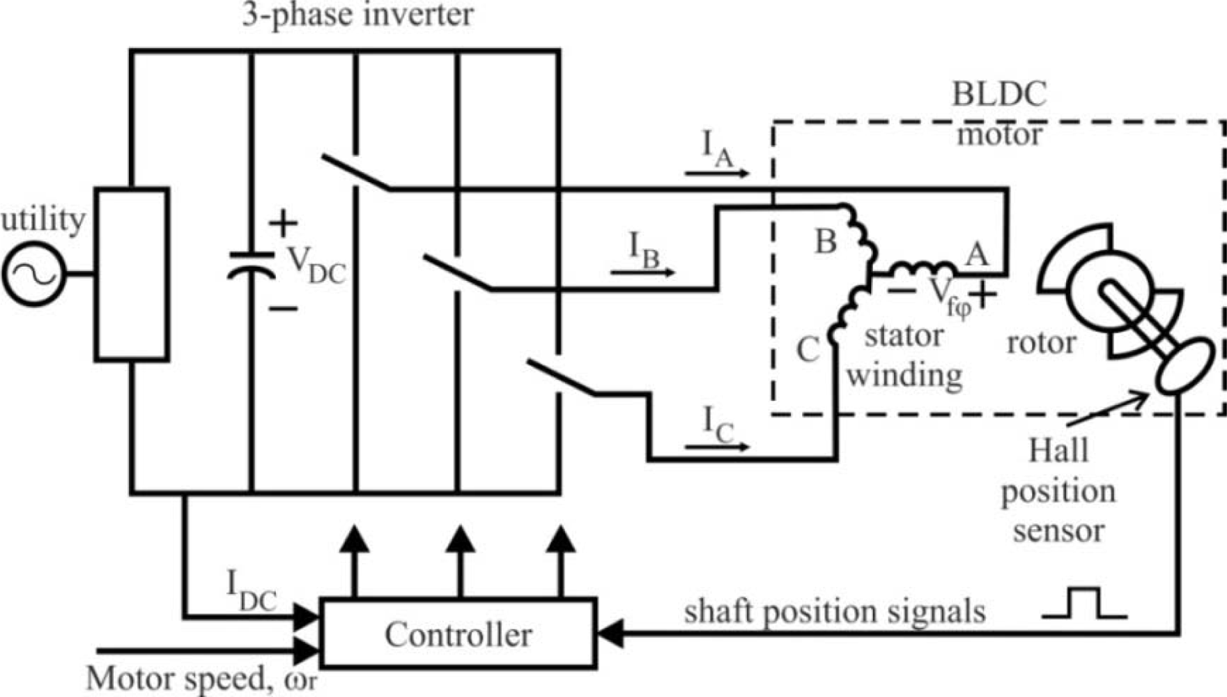
Sensors Free Full Text Position And Speed Control Of Brushless Dc Motors Using Sensorless Techniques And Application Trends Html

Sensors Free Full Text Position And Speed Control Of Brushless Dc Motors Using Sensorless Techniques And Application Trends Html

How To Do Motor Terminal Connection Electrical Mastar

How To Do Motor Terminal Connection Electrical Mastar

Pin On Diy

Pin On Diy

Transmission Cooler Mounting Position Transmission Cooler Transmission Positivity

Transmission Cooler Mounting Position Transmission Cooler Transmission Positivity

What Is A Electric Motor Actuator Electric Motor Actuator Electricity

What Is A Electric Motor Actuator Electric Motor Actuator Electricity

8 Northstar V8 Engine Diagram Di 2020 Taurus Diagram Ford

8 Northstar V8 Engine Diagram Di 2020 Taurus Diagram Ford

Outboard Motor Bracket Instructions Product Manual Anchoring Com

Outboard Motor Bracket Instructions Product Manual Anchoring Com

Fastrak Standard Installation Instructions The Toll Roads

Fastrak Standard Installation Instructions The Toll Roads

Pin On Wiring Diagram

Pin On Wiring Diagram

Source : pinterest.com